
We have a shiny new blog, so I thought I would post something cool and interesting to get it started.
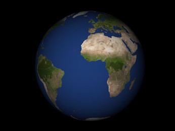
One of the topics that I find really fascinating is using shaders to fake 3D objects and lighting in a 2D world. I casually asked my wife and a couple of other people if they thought it would make a good first blog post that people would find interesting and exciting. Their reactions were a bit less than enthusiastic. Something along the lines of "hmmm, seriously?". So, clearly, I need to meet more geeks. I mean, how could you not be excited about this? Look at it (and move the mouse around the planet to change the lighting).
Now the interesting bit is that this is not, by any means, a 3D object. It looks like it, but all I'm doing is drawing a sprite (so a plain, flat square) with a clever shader that does a bit of maths, and makes it look like a rotating sphere in a 3D world.
Traditionally to draw a sphere you generate some 3D geometry, send this to the GPU as a vertex buffer (importantly, this will never be a sphere, just an approximation, as it will have to consist of a finite number of triangles); the GPU then runs a vertex shader for each vertex in the geometry, and generates fragments (pixels). Then for each pixel it runs a pixel shader.
Here we're skipping a few steps: I just started a new project in WADE, added a quad to the scene and started editing its pixel shader. You can probably do this with any engine that supports WebGL, or with vanilla JavaScript if you're so inclined. The nice thing with WADE is that you can see what's happening in real-time as you type - just be sure to select the "Always Draw" button near the top of the Sprite tab.
So let's start writing a shader. Let's start with something simple first: instead of a quad, we want to draw a circle. By default, all shaders in WADE have access to a vector called uvAlphaTime. It's a vector that contains several pieces of information, but now we're only interested in the x and y components, that represent uv coordinates (also known as texture coordinates). These vary uniformly from 0,0 (top-left corner of the quad) to 1,1 (bottom-right). We want to re-scale these coordinates, so instead of varying from 0 to 1 the go from -1 to 1. Easy enough:
vec2 uv = (uvAlphaTime.xy - 0.5) * 2.;
Now that we've done this, the length of this uv vector will be, for each pixel, exactly the distance from the centre. I'm calling this variable radius.
float radius = length(uv);
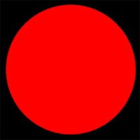
Let's define two colours now: one to show for pixels that are inside the circle (so whose radius is <= 1), and one for those that are outside the circle. It makes sense to make the outside color fully transparent, and I'm making the inside color temporarily red:
	vec2 uv = (uvAlphaTime.xy - 0.5) * 2.;
	float radius = length(uv);
	vec4 inside = vec4(1., 0., 0., 1.);
	vec4 outside = vec4(0.);
	gl_FragColor = radius <= 1.? inside: outside;
 We've turned a square into a circle, but that's still very much a 2D object. How do we turn a circle into a sphere? Really, we could pretend that this is actually a sphere - when it's projected onto a 2D plane (the screen), it just looks like a circle. It feels flat because to have proper lighting on it, we would need to know what the 3D position of the points that end up on the screen actually is, and what the normal associated with each point is. So the question is: what are the 3D coordinates of each point of our circle? To simplify things, let's ignore the position of the sphere in the world, so everything is relative to the sphere's center. And let's ignore its size, let's just say that the sphere has a radius of 1.
If we have the x and y coordinates of each point (which we do, it's our uv vector), then we can easily use the sphere's equation x2 + y2 + z2 = 1. From this we can easily calculate z, and construct a 3D vector (that I will call normal) that goes from the center of the sphere to each pixel:
vec3 normal = vec3(uv.x, uv.y, sqrt(1. - uv.x*uv.x - uv.y*uv.y));
With this vector we can do some interesting stuff: we can start applying 3D lighting to our object. The simplest lighting model is what is known as NdotL: it's the dot product of a normalized light vector and a normalized surface normal. We do have a normalized surface normal, it's our normal vector that we just calculated. What about the normalized light vector? We could hard-code this in the shader, but it's better to have it a shader uniform, so we can easily change values from CPU code, or manually, without having to edit the shader code. So I'm adding a vec3 uniform called lightDir, and just to test things I'm going to set it to [-0.4, -0.3, 0.5]. I just made these numbers up, use anything you like - though use a positive z to make sure that the light comes from the same side of the screen that we're looking from.
You'll notice it's not normalized - it's just more convenient to normalize this in the shader (though not optimal for performance, but I do like the convenience). So let's normalize it in our shader:
vec3 l = normalize(lightDir);
Now let's compute our NdotL lighting coefficient and use that as our inside color:
	vec3 l = normalize(lightDir);
	vec2 uv = (uvAlphaTime.xy - 0.5) * 2.;
	float radius = length(uv);
	vec3 normal = vec3(uv.x, uv.y, sqrt(1. - uv.x*uv.x - uv.y*uv.y));
	float ndotl = max(0., dot(normal, l));
	vec4 inside = vec4(ndotl, ndotl, ndotl, 1.);
	vec4 outside = vec4(0.);
	gl_FragColor = radius <= 1.? inside: outside;
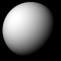 It's starting to look like a sphere! Now to make things more interesting I'm going to add this bit of code to app.js to change the light direction based on the mouse position relative to the center of the sphere. Just to be clear, this code is executed on the CPU, and has nothing to do with our shader - it merely sets the value of the light direction. Note that to make this work, your scene object with the square sprite must be called 'sphere'.
	wade.app.onMouseMove = function(data)
	{
		var sphere = wade.getSceneObject('sphere');
		var size = sphere.getSprite().getSize();
		var pos = sphere.getPosition();
		var dist = wade.vec2.sub(data.screenPosition, sphere.getPosition());
		dist.x = Math.min(1, dist.x / size.x);
		dist.y = Math.min(1, dist.y / size.x);
		var lightDir = sphere.getSprite().lightDir;
		lightDir[0] = dist.x;
		lightDir[1] = dist.y;
		lightDir[2] = 1 - dist.x*dist.x - dist.y*dist.y;
	};
Now you can move the mouse around the change the light direction, and see how this affects the lighting of the sphere.
Of course this would look better if it had a texture on it. I have selected this nice earth texture, courtesy of solarsystemscope.

As you may know, in WADE you access a sprite's texture through the shader uniform called uDiffuseSampler. So after importing this texture into our WADE project and assigning it to our sprite, we could do:
	vec3 texColor = texture2D(uDiffuseSampler, uv, 0.).xyz;
	vec3 lightColor = vec3(ndotl) * texColor;
	vec4 inside = vec4(lightColor, 1.);
But it doesn't look right: we are just drawing the texture as if it was applied to a flat circle, so on the screen we can see a section of it, but it looks flat - if it was applied to a sphere, there would be some distortion. To make it look correct, we should not use our flat uv vector to sample the texture, but distort it so we appear to sample from the surface of a sphere. The maths may appear to be a bit complicated if you're not very familiar with trigonometry, but it boils down to this relatively simple formula to calculate the spherical projection of our normal vector:
	const float PI = 3.141592653589793238462643383;
	vec2 texCoords = vec2(0.5 + atan(normal.x, normal.z) / (2.*PI), asin(normal.y) / PI - 0.5);
	vec3 texColor = texture2D(uDiffuseSampler, texCoords, 0.).xyz;
Very cool, but a bit too static for my liking. Adding some rotation, luckily, is extremely easy: it's just a case of adding an ever increasing value to the x component of our texCoords vector. I am going to use the time value that is available through the uvAlphaTime vector:
	float rot = uvAlphaTime.w * 0.1;
	vec2 texCoords = vec2(0.5 + atan(normal.x, normal.z) / (2.*PI) + rot, asin(normal.y) / PI - 0.5);
So here's the full shader for a rotating 3D sphere with simple NdotL lighting:
	const float PI = 3.141592653589793238462643383;
	vec3 l = normalize(lightDir);
	vec2 uv = (uvAlphaTime.xy - 0.5) * 2.;
	float radius = length(uv);
	vec3 normal = vec3(uv.x, uv.y, sqrt(1. - uv.x*uv.x - uv.y*uv.y));
	float ndotl = max(0., dot(normal, l));
	float rot = uvAlphaTime.w * 0.1;
	vec2 texCoords = vec2(0.5 + atan(normal.x, normal.z) / (2.*PI) + rot, asin(normal.y) / PI - 0.5);
	vec3 texColor = texture2D(uDiffuseSampler, texCoords, 0.).xyz;
	vec3 lightColor = vec3(ndotl) * texColor;
	vec4 inside = vec4(lightColor, 1.);
	vec4 outside = vec4(0.);
	gl_FragColor = radius <= 1.? inside: outside;
It's looking very neat, but you'll probably notice something really annoying: when the sphere rotates by 180 degree, a horrible seam becomes visible. This happens when there is a discontinuity, and the X value of the texture coordinate vector crosses the [0, 1] boundary. Ultimately this is due to the hardware-accelerated filtering of the texture, something that the GPU can do, and that WADE does automatically when the texture size is a power-of-two, in order to speed up the drawing. While this has got many advantages, it isn't always ideal: case in point, it makes a horrible seam appear in our otherwise perfect sphere. But fear not, we just have to disable the hardware filtering to make our sphere truly perfect. You could write some JavaScript to do that, but I'd say that to keep it simple we could change our texture to this:

It's exactly the same texture, but it's 1022x511, so not a power of two, and therefore no hardware filtering can be applied to it. The only modification that we need in our shader is this:
vec2 texCoords = fract(vec2(0.5 + atan(normal.x, normal.z) / (2.*PI) + rot, asin(normal.y) / PI - 0.5));
By doing fract(...) we take the fractional part of the vector, which otherwise would not be in the [0, 1] range and for non-power-of-two textures, being outside the [0, 1] range is bad, because these textures are clamped and can not wrap around. Effectively we do the wrapping-around manually by taking the fractional part of the texture coordinates.
All in all we have achieved a pretty cool result, and this has been a rather lengthy first blog post! Hopefully you've enjoyed it - I'll be back with more cool shader tricks soon.

